 In today’s tutorial, we’re going to learn how to create our very own video card icon, using nothing more than the basic shapes and tools that you probably already work with on a daily basis.
So, assuming you already have Illustrator up and running let’s jump straight into it!
Tutorial Details: Video Card Icon
- Program: Adobe Illustrator CS6 – CC
- Difficulty: Beginner
- Topics Covered: Design Theory, Compositional Construction, Shape Alignment, Grid Positioning
- Estimated Completion Time: 40 Minutes
Final Image: Video Card Icon

Step 1
As with every new project, start by first setting up a New Document by going over to File > New (or using the Control-N keyboard shortcut), which we will adjust as follows:
Number of Artboards: 1
- Width: 128 px
- Height: 128 px
- Units: Pixels
And from the Advanced tab:
- Color Mode: RGB
- Raster Effects: Screen (72ppi)
- Preview Mode: Default
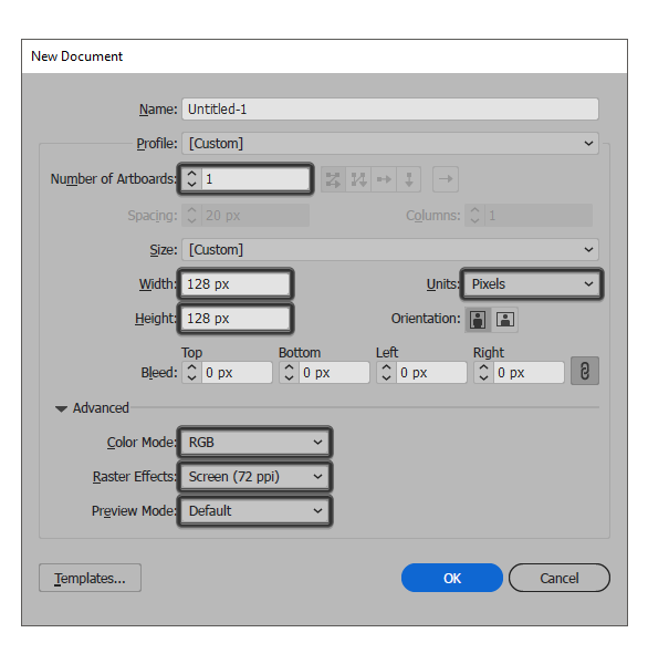
Quick tip: most of the indicated settings can be automatically triggered if you set the document’s Profile to Web, the only one that you’ll have to manually adjust being the Artboards Size (Width x Height).
Step 2
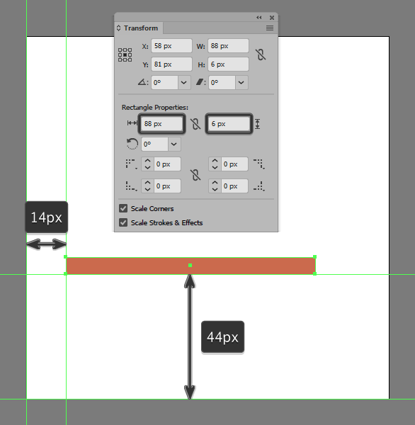
Once we’ve set up our project file, we can start working on the actual icon, by creating the main shape for its circuit board using an 88 x 6 px rectangle, which we will color using #cc6a4c and then position at a distance of 14 px from the Artboard’s left edge, and 44 px from its bottom one.
Step 3
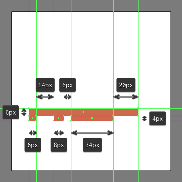
Create the board’s “teeth” using three 4 px tall rectangles (6 x 4 px > 8 x 4 px > 34 x 4 px), which we will color using the exact same color #cc6a4c, and then position underneath the larger rectangle as seen in the reference image.
Step 4
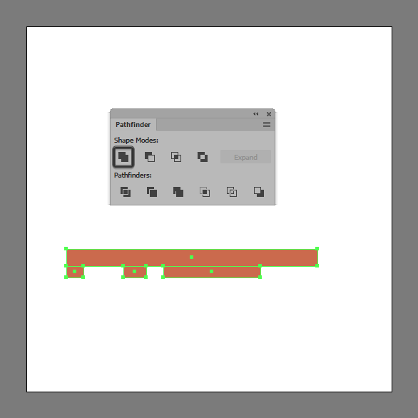
Select and combine all four shapes into a single larger object using Pathfinder’s Unite Shape Mode.
Step 5
Give the resulting shape an outline using the Stroke method, by creating a copy of it (Control-C) which we will paste in front (Control-F) and then adjust by first changing its color to #2c2c2d, and then flipping its Fill with its Stroke (Shift-X) making sure to set its Weight to 4 px.
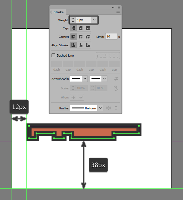
Step 6
Add the little insertion to the bottom of the board’s third tooth using a 22 x 4 px rectangle (#2c2c2d). Once you’re done, select and group all three shapes together using the Control-G keyboard shortcut before moving on to the next step.
Step 7
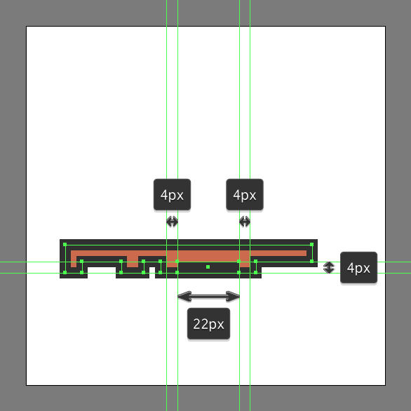
Add the smaller golden pin section using an 8 x 6 px rectangle (#dda664) with a 4 px thick outline (#2c2c2d), which we will group (Control-G) and then position below the board’s second tooth so that their outlines end up overlapping.
Step 8
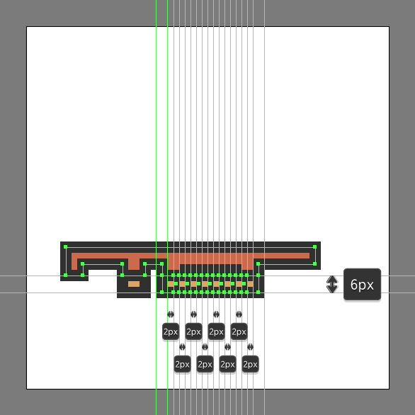
Add the larger pin section using a 34 x 6 px rectangle (#dda664) with a 4 px thick outline (#2c2c2d), on top of which we will add a group of seven 2 x 6 px rectangles (#2c2c2d) horizontally stacked at a distance of 2 px from one another). Once you’re done, select and group (Control-G) the current section’s composing shapes together before moving on to the next step.
Step 9
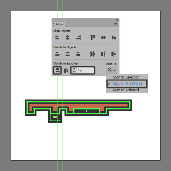
Create the locking clip using a 4 px thick Stroke line (#2c2c2d) which we will position onto the bottom-right side of the circuit board. Once you’re done, select and group (Control-G) all of the shapes that we have so far, before moving on to the next step.
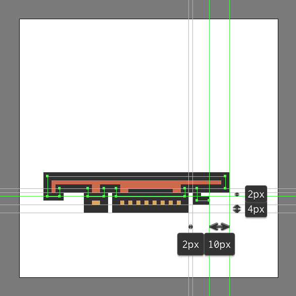
Step 10
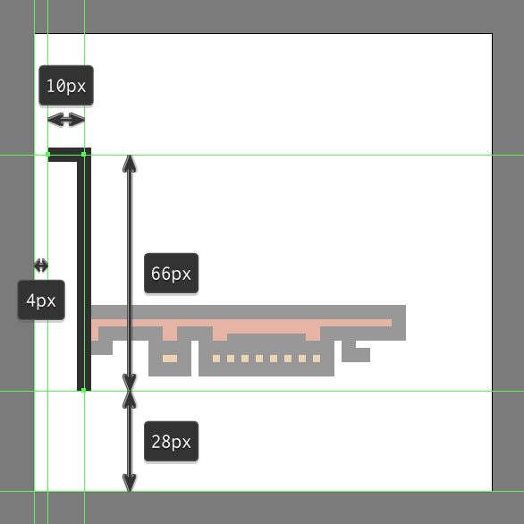
Start working on the card’s IO by creating its shielding bracket using a 4 px thick Stroke line (#2c2c2d), which we will position onto the left side of the circuit board.
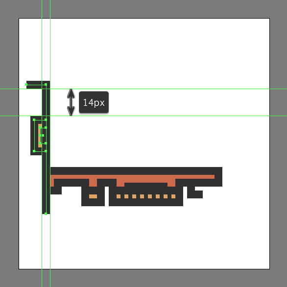
Step 11
Add the DVI connector using a 6 x 16 px rectangle (#dda664) with a 4 px thick outline (#2c2c2d), onto the right side of which we will add a 3 x 8 px rectangle (#2c2c2d). Group all three shapes together (Control-G), and then position them onto the left side of the shield, at a distance of 14 px from its top edge.
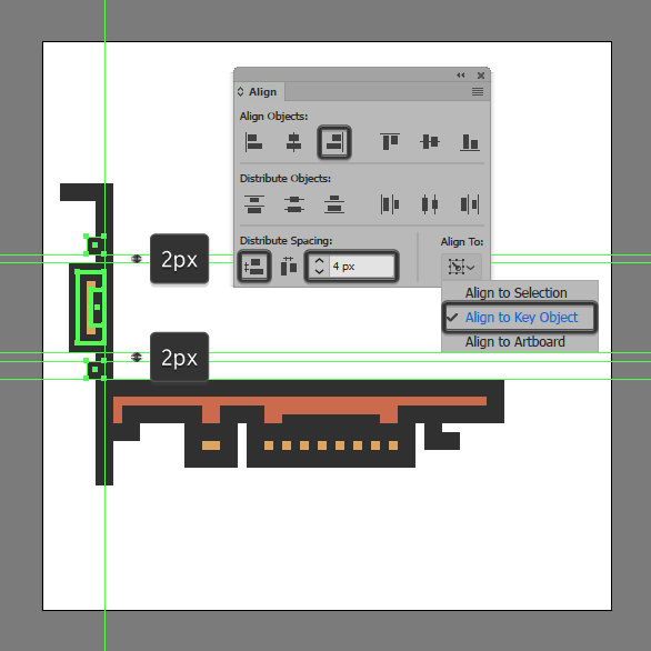
Step 12
Add the little screw locks using two 4 x 4 px squares (#2c2c2d), which we will vertically position at a distance of 4 px from the DVI connector’s top and bottom edges. Before you move on, select and group all of the shield’s composing shapes together using the Control-G keyboard shortcut.
Step 13
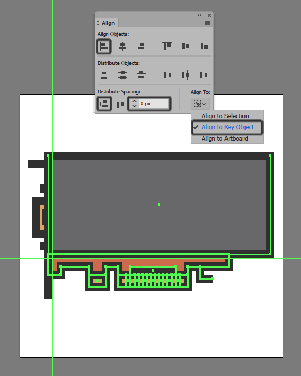
Create the card’s main body using a 108 x 48 px rectangle (#68686b) with a 4 px thick outline (#2c2c2d), which we will group (Control-G) and then position on top of the smaller circuit board, aligning it to its left edge.
Step 14
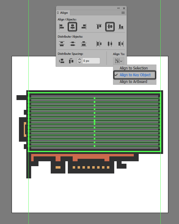
Add the horizontal detail lines using fourteen 108 x 1 px rectangles (#2c2c2d) vertically stacked at 2 px from one another, which we will group (Control-G) and then center align to the larger body. Once you have them in place, select them and the main body and create another group using the Control-G keyboard shortcut.
Step 15
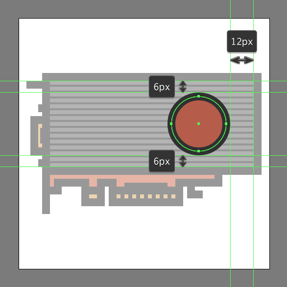
Create the fan’s outer section using a 28 x 28 px circle (#b75d48) with a 4 px thick outline (#2c2c2d), which we will group (Control-G) and then center align to the larger body, positioning them at a distance of 12 px from its right edge.
Step 16
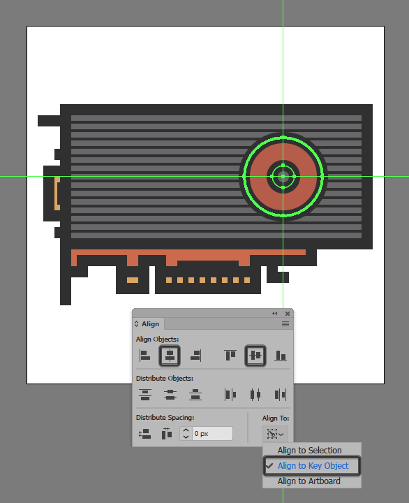
Add the fan’s inner section using an 8 x 8 px circle (#68686b) with a 4 px thick outline (#2c2c2d), which we will group (Control-G) and then center align to the previously grouped shapes.
Step 17
Finish off the fan and with it the icon itself by adding the inner ring using an 18 x 18 px circle with a 2 px thick Stroke (#2c2c2d), which we will center align to its larger section. Once you’re done, select and group (Control-G) all of the fan’s composing shapes, doing the same for the upper body and the entire icon afterwards.
![]()
Great Job!
There you have it guys, an easy step-by-step approach on how to design your very own video card icon using nothing more than some basic geometric shapes and tools.
Author: Andrei Ștefan
Just another coffee addict / pixel grinder, creating colorful projects one pixel at a time.


good